AS 1768 earthing: the earth termination network under AS 1768:2021
AS 1768:2021 recommends that the earth termination network read 10 ohms or less, measured before it is bonded to services outside the lightning protection system. That figure is a target, not a pass mark. The firm rules are about bonding, burial depth and records.
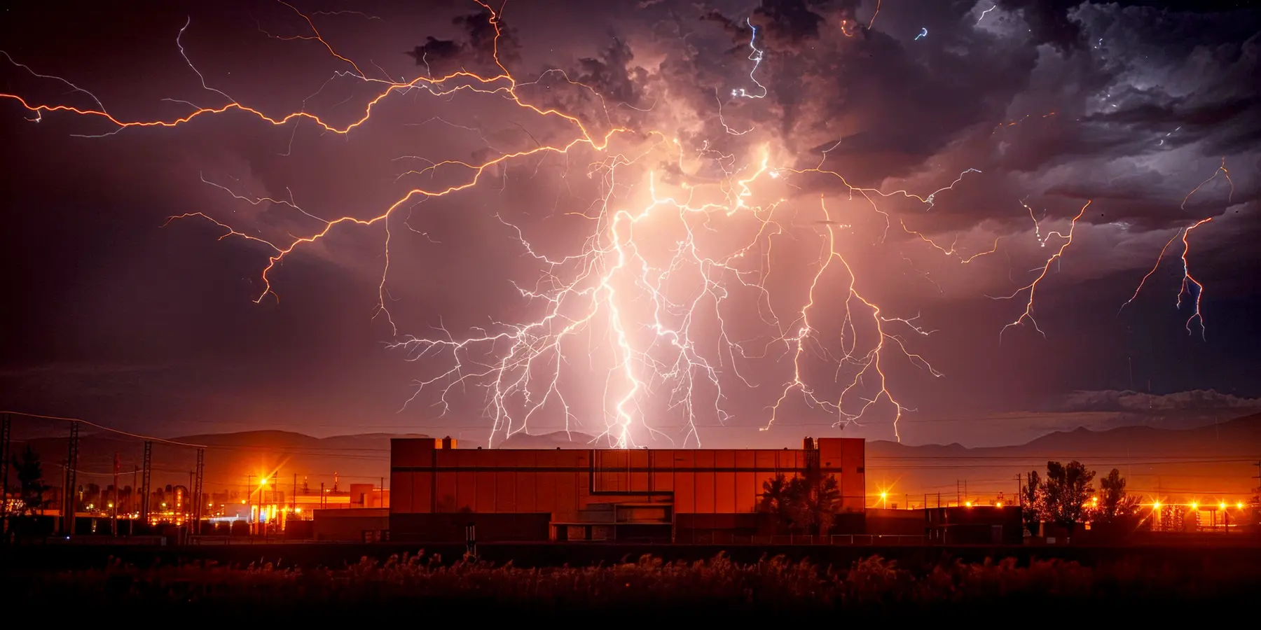
AS 1768 earthing is the earth termination network of Clause 3.5 of AS 1768:2021: the buried conductors, electrodes and bonded foundations that carry a strike's current into the ground.
AS 1768:2021 is the Australian lightning protection standard from Standards Australia. It replaced AS/NZS 1768:2007 and, unlike its predecessor, is published for Australia alone (Preface). Earthing sits in Clause 3.5 of its Section 3, beside the air terminals and downconductors, with the informative Appendix E behind it for design and testing.
Below, "must" marks a shall in the standard and "recommends" marks a should. Every point cites the clause it comes from, so you can check it against your own copy. Lumex is independent of Standards Australia, and you need the published standard to design or certify an installation.
Reviewed clause by clause against AS 1768:2021 by the Lumex team, September 2026.
What the earth termination network is for
Under AS 1768:2021, the first job of the earth termination network is to get rid of the lightning energy safely. Its second job is to keep step and touch voltages low in and around the structure (Clause 3.5.1). The standard defines the network as the conductors and electrodes whose purpose is to pass the strike current into the body of the earth (Clause 1.3.16), and an earth electrode as the part of that network in direct contact with the soil (Clause 1.3.13).
Appendix E splits a lightning protection system into interception, conduction and dissipation (Clause E.1), and earthing is the dissipation stage. Its effectiveness turns on the network's impedance to earth: lower impedance means a smaller earth potential rise and lower step and touch voltages (Clause E.2.1).
Clause 3.5.1 also sets the default approach for most modern buildings. Conductive foundations of concrete and steel can serve as the whole earth termination network, provided they meet the conditions of Clause 3.5.3. Where they fall short, you add dedicated electrodes and bond them to the foundation steel. One hard rule sits in this clause too: aluminium conductors must never be buried directly in the ground.
The earthing requirements you must meet
Clause 3.5.2 splits its content into firm requirements and points to consider. The firm ones are short and specific.
One bonded earthing system
Every earthing system belonging to the structure is bonded to the earth termination network, directly or through gas discharge devices. Where an electrical earth electrode exists, the lightning earth is bonded to it too.
Dedicated downconductors end at an electrode
Where you install dedicated downconductors rather than using the structure's own steel, each one is bonded to an earth electrode.
500 mm of cover for horizontal electrodes
Horizontal earth electrodes go at least 500 mm below finished level. The conductor that joins unbonded natural components should sit at the same depth.
Metallic services bonded in
All metallic services are bonded to the earth termination network. Clause 3.6.2(c) adds where: at the point where gas, water and similar services enter the structure.
The same clause recommends interconnecting multiple vertical electrodes and labelling accessible dedicated electrodes as a lightning earth not to be disconnected. Footings, steel piles and screw anchors count as natural earth components unless a continuous isolating barrier cuts them off from the soil, and unbonded natural components must be joined by a horizontal electrode.
What earth resistance does AS 1768 require?
AS 1768:2021 recommends an earth resistance of 10 ohms or less. It does not make that figure a requirement. Clause 3.5.3 says the network should not exceed 10 ohms to earth, measured before it is bonded to any service that is not part of the lightning protection system. The next sentence accepts that some soils make this unreachable, and asks instead for the lowest practical value, using the impedance reduction measures of Clause E.3.7.
The figure appears again in the testing list of Clause 5.2. There, the whole network and any electrode that is not interconnected should read under 10 ohms, while individual electrodes inside an interconnected network may read higher (Clause 5.2(b) and (c)). So the target applies to the network as a system, not to each rod.
Informative Appendix E goes further. It recommends the lowest impedance you can reach, at or below 10 ohms, because it affects side flashes and sparking inside the structure (Clause E.2.2). But it also says that bonding every piece of equipment together per Clause E.3.9 lifts everything to the same potential, and that this can protect well even where the earth impedance is above 10 ohms. It names mountain top communications sites as the typical case.
| Where 10 ohms appears | What AS 1768:2021 says, in our words | Force |
|---|---|---|
| Clause 3.5.3 | The network should be at most 10 ohms before bonding to services outside the lightning protection system; otherwise reach the lowest practical value | Recommendation |
| Clause 5.2(b) | Test results for the network, and for electrodes that are not interconnected, should be under 10 ohms | Recommendation |
| Clause 5.2(c) | Single electrodes within the network may exceed 10 ohms | Permission |
| Clause E.2.2 | Keep impedance as low as possible, at or below 10 ohms; bonding can still protect a site where it is above 10 ohms | Informative |
| Clause E.3.2 | Adding electrodes until a low frequency meter shows 10 ohms is named as a common design error | Informative |
| Clause E.3.7.3 | Backfills are an option in moderate to high resistivity soil where the 10 ohm impedance target is unlikely | Informative |
Electrode arrangements and where each suits
AS 1768:2021 does not prescribe one layout. It describes the parts you can use and the conditions each suits, spread across Clause 3.5 and Appendix E.
| Arrangement | When it fits | Clause |
|---|---|---|
| Reinforced concrete footings and foundation steel | Most structures with conductive foundations; a permanent, spread out earth at little extra cost | 3.5.1, 3.5.2(A), E.4.4 |
| Steel piles, screw anchors and other large conductive supports | Structures standing on metal supports with no isolating barrier around them | 3.5.2(B) |
| Driven or drilled vertical rods | Sites where a low resistivity layer such as clay or the water table lies at depth | 3.5.2(i), E.4.2 |
| Buried horizontal strip | Shallow soil over rock, where a rod cannot be driven | 3.5.2(c), E.4.3 |
| Rod at the injection point with radials and end rods | A dedicated network; rods spaced at least twice their driven depth apart | E.3.7.1(b), E.3.7.2 |
| Ring earth | Tying vertical rods together, and bonding services that do not enter at one point | E.3.9.4 |
| Low resistivity backfill | Moderate to high resistivity soil where the 10 ohm target is unlikely | E.3.7.3 |
Material sizes come from Table 3.3, which sets a minimum section of 35 mm² for earth electrodes and buried conductors; a 12 mm earth rod is one of its examples. Note 2 of the table points out that electrodes are often made larger than the minimum to allow for corrosion and damage from digging, and Note 3 recommends stainless steel in harsh settings such as saline soil.
Why impedance matters more than a low frequency reading
Lightning current rises at a rate of the order of 10 kA per microsecond (Clause E.3.7.1). At that rate the earth network acts less like a simple resistor and more like a leaky transmission line, with resistance, inductance and capacitance. That is why Appendix E keeps talking about impedance while Clause 3.5.3 talks about resistance. The design aim in Clause E.3.1 is a network whose impedance is not much higher than its low frequency resistance.
The tool for that is the critical length of Clause E.3.2. Beyond a certain length, extending an electrode no longer lowers the impedance a strike sees, however much it improves a low frequency meter reading. Critical length grows with soil resistivity. Table E.1 gives approximate figures, for example about 10 m in 100 ohm metre soil and about 35 m in 1 000 ohm metre soil. A network designed within that limit is what the standard calls a compact earth termination network (Clause 1.3.6).
Soil comes first. Clause E.3.5 recommends measuring how resistivity changes with depth before any layout, so rods can reach a low resistivity layer if one exists. Table E.2 lists typical values for soils, rock and water, and the four equations of Clause E.3.6 estimate the resistance of a rod, a horizontal electrode and a ring.
To lower impedance, Clause E.3.7.1 lists flat strip in place of round conductor, a centre feed, footings and slabs as extra paths, and low resistivity backfill. Clause E.3.7.3 warns that bentonite backfill needs moisture, so dry season readings can come in higher than expected.
Equipotential bonding and side flashing
When the lightning protection system takes a strike, its potential rises, and the current may jump to nearby metal instead of following the intended path. AS 1768:2021 calls this side flashing and requires one of two remedies: isolation under Clause 3.6.3, or equipotential bonding under Clause 3.6.2 (Clause 3.6.1).
Bonding connects metal parts so they rise together. As a minimum, Clause 3.6.2 requires prominent roof plant to be bonded to the system, metal that could endanger life, such as balcony rails, ladders and walkways, to be bonded too, and metallic services such as gas and water to be bonded to the earth termination where they enter the structure. Any bond, and the item bonded, must be able to carry the share of lightning current it may take. Clause 3.5.3 also requires equipotential bonding to be made either directly or through SPDs; for how those devices are chosen and fitted, see surge protection under AS 1768.
Isolation is the alternative: keep the system far enough from other metal, through air or insulation, that no breakdown occurs. Equation 3.6.3 gives the separation distance as the protection level factor times the downconductor factor, divided by the insulation factor, times the length of conductor back to the nearest bonding point or the earth termination. Table 3.2 gives simplified values for those factors.
Appendix E gives the practical detail. Clause E.3.9.1 recommends keeping the potential difference under 1.5 kV during a direct strike. Because a bonding conductor develops about 1 kV per metre under typical lightning transients, that points to a conductor no longer than 1.5 m between the bonded part and the main earth bar. Clause E.3.9.2 describes a bonding bar near the main switchboard, linked to the main earth bar through a disconnect link. Table 3.3 sets major bonding conductors at 16 mm² and minor ones at 6 mm². Clause E.3.8 recommends at least 3 m between the lightning earth and other earthed services such as pipelines.
How is earth resistance measured?
Clause E.5.1 recommends measurement at three stages: soil resistivity at design, impedance at commissioning, and impedance and integrity through the life of the system.
Soil resistivity by the Wenner method
Four test electrodes in a line, equally spaced, shallow compared with their spacing. Current flows between the outer pair and voltage is read across the inner pair. Widening the spacing about a fixed centre reveals how resistivity changes with depth. Start at 1 m or more and extend to at least the size of the planned network.
Continuity with four probes
Continuity tests check that air terminals, downconductors, bonds and the main earth bar are joined. At the low values found in earth networks, under 2 ohms, lead and contact resistance distort a two wire reading, so a four probe measurement is recommended.
Fall of potential
The method Clause 3.5.3 names as most common. Current flows from the network to a distant current electrode, and a voltage probe moves outward until the reading levels off. In uniform soil the current electrode sits at least 5 to 10 times the network's size away, and the 61 % rule may apply. Above 500 ohm metres, Equation E.5.5.1(2) ties the distance to the resistivity and the network's size.
Selective, stakeless and surge impedance
Variants for when disconnecting the network is unsafe or impractical, or for testing lightning performance directly. Each has limits, and Clause E.5.6.1 says no single method suits every site.
Two cautions from Appendix E catch people out. A current electrode set too close reads lower than the truth, so the result looks better than it is (Clause E.5.5.1, Note 1). And a network bonded to the power supply neutral usually reads far lower at low frequency than it performs for lightning, which surge impedance testing exposes (Clause E.5.6.4).
Testing, records and inspection intervals
Testing starts before the building is finished. Clause 5.2 requires the system to be tested during construction when natural components are used, or on installation of dedicated components, and again over its service life. Clause 3.5.3 adds that when structural footings form the earth, their resistance must be measured and recorded during construction, while each footing can still be tested on its own. The same applies to dedicated electrodes. Where buried or cast in parts cannot be seen afterwards, records and photographs must show how they were installed and joined (Clause 5.2).
Clause 5.2 recommends testing at intervals of no more than two years, and Clause 5.4.4 recommends the same ceiling for inspection, noting that some locations, such as a marine site with fast corrosion, may need more frequent visits. The maintenance program recommended in Clause 5.4.2 covers measuring the resistance of the earth termination system and, where they can be reached, of individual electrodes. Clause 5.3 recommends keeping records on site, including the test conditions, date and results for earth resistance and continuity, the soil conditions and any special earth arrangements.
In practice, an inspector checking the earthing asks for three things: the footing or electrode resistance readings taken during construction (Clause 3.5.3), the records and photographs of buried joints (Clause 5.2), and the date of the last test, set against the two year interval.
In dense city centres, buried services can make a meaningful earth resistance test impossible, and Clause E.3.3 Note 3 advises testing continuity to the network during construction instead.
Corrosion, and earthing where there is a risk of explosion
An earth network is bare metal in wet ground, so corrosion decides its life. Clause 3.7.5 caps the difference in anodic index between the building materials and the lightning protection components at 0.5 V, and requires joints between dissimilar metals, such as aluminium to copper, to be protected. Its Note 3 suggests 0.15 V in harsh settings such as the coast. Clause E.4.1 warns that soil under 50 ohm metres shortens electrode life, because corrosion speeds up as resistivity falls.
Appendix J, which is normative, adds rules for structures that hold explosives, or where flammable gas, vapour or combustible dust could be present. Equipment grouped on a raised concrete plinth must be bonded to a common earth connection (Clause J.2.2). Earth bonding points must be of the same or a compatible metal as the structure and sit at least 500 mm above finished level (Clause J.2.3). Steel tanks holding liquids that can form an explosive atmosphere must have their shells earthed to Section 3, with one earth connection per 20 m of perimeter. A group of small tanks may share electrodes, provided each tank keeps at least two independent paths to earth, and every entering pipe is bonded to the tank (Clause J.4.1.1.1). For the wider picture on these sites, see lightning protection for oil, gas and hazardous areas.
Common earthing mistakes an inspector will find
Most AS 1768 earthing faults found at inspection come from treating 10 ohms as the whole job, or from bonds that were never made.
Chasing 10 ohms with length
Laying ever more conductor until the meter shows 10 ohms, past the critical length where it no longer helps a strike. Clause E.3.2 names this as a common error.
Measuring after service bonding
Clause 3.5.3 sets the target before bonding to other services. A bonded low voltage neutral gives the current another path and a false reading, as Clause E.3.4 warns.
Missing point of entry bonds
Gas and water services entering without a bond to the earth termination, or an earth network left unbonded to the electrical earth electrode, against Clauses 3.6.2(c) and 3.5.2(e).
No footing records
Foundations used as the earth with no resistance readings taken during construction. Once the slab is poured, Clause 3.5.3's requirement can no longer be met.
Buried aluminium and mixed metals
Aluminium laid directly in soil, which Clause 3.5.1 forbids, or aluminium joined to copper earthing with no protection at the joint, against Clause 3.7.5.
Tests left to lapse
Earth readings last taken at handover. Clause 5.2 recommends testing at least every two years, and Clause 5.3 lists soil conditions among the records, so later readings can be compared.
The risk decision that comes before the earthing
Lumex does not design earth networks or certify installations. It runs the step that decides whether a lightning protection system is needed at all: the AS 1768:2021 risk assessment, with R1 to R4 each judged against its own tolerable value and the least protection found under Clause C.3.4.2. Every figure shows its working, in a report the engineer signs off.
Wherever a lightning protection system is part of the answer, the result reminds you to bond metallic services such as gas and water at the point of entry, under Clause 3.6.2(c), because the risk inputs have no place to record it. Each assessment also carries a review due date, 24 months after it is done for AS 1768, which matches the two year interval Clauses 5.2 and 5.4.4 recommend, with a reminder when it falls due.
Start there: run the AS 1768:2021 risk assessment to learn whether a lightning protection system is needed at all, or compare the options on which lightning standard applies. Related guides:
AS 1768 earthing, questions answered
What earth resistance does AS 1768 require?
Is 10 ohms mandatory under AS 1768:2021?
What is the Australian standard for earthing a lightning protection system?
How is earth resistance measured under AS 1768?
Must the lightning earth be bonded to the electrical earth?
Can building foundations be used as the lightning earth?
How deep must earth electrodes be buried under AS 1768?
How often should AS 1768 earthing be tested?
Lumex computes the method of the standard you choose, IEC 62305-2:2024, AS 1768:2021 or NFPA 780-2026, and shows the working. It does not certify a structure. You may not issue or submit a Lumex output until a competent person, qualified where the structure is located, has reviewed the inputs and the result and signed it.
AS 1768:2021 Table 2.1 sets a tolerable value for each type of loss, and the owner chooses the one for economic loss. Every AS 1768 assessment in Lumex states the values that applied.
Get started today