Separation distance calculation under IEC 62305-3
The separation distance s is how far unbonded metal must stay from a lightning protection system so a strike cannot spark across. This guide sets out the IEC 62305-3:2024 formula, where each coefficient comes from, a worked example, and how NFPA 780 and AS 1768 do the same job.
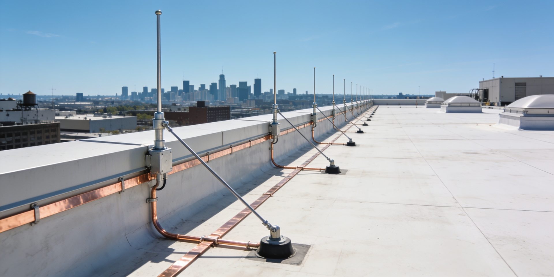
The separation distance s is the minimum gap between a lightning protection system and any unbonded metal near it.
When lightning current runs down an air termination and a down conductor, that conductor rises to a very high voltage compared with the pipes, cable trays, handrails and roof plant around it. If one of those parts is too close and is not bonded, the voltage can jump the gap as a spark, which can start a fire or put people at risk. IEC 62305-3:2024 clause 6.3 calculates how big the gap must be.
The calculation is short. Three coefficients and one length go in, and one distance comes out: s = (ki / km) × kc × l. The care goes into choosing each input. This guide explains every term, gives the values IEC 62305-3:2024 sets for them, works one example, and shows how NFPA 780-2026 and AS 1768:2021 answer the same question with formulas of their own. For where the separation distance sits in a full design, read lightning protection system design.
Two ways to calculate s
IEC 62305-3:2024 gives a simplified approach and a general one. Both multiply the same class coefficient by the length of conductor the current has travelled, and both divide by the same material coefficient. They differ in how they treat the current sharing.
- Simplified approach, clause 6.3.2, equation (6): s = (ki / km) × kc × l. One current-sharing coefficient kc applies to the whole length l.
- General approach, clause 6.3.1, equation (5): s = (ki / km) × (kc1 × l1 + kc2 × l2 + ... + kcn × ln). The path is split into segments, and each segment carries its own share of the current.
The simplified approach is the one most designs use, because Table 13 gives kc from the number of down conductors alone. The general approach earns its extra work on tall or meshed systems, where the current spreads out as it travels down and a single kc would overstate the distance needed lower on the structure.
Where ki, km and kc come from
| Coefficient | What it depends on | Values | Source |
|---|---|---|---|
| ki | The class of LPS, which follows from the lightning protection level | Class I: 0.08. Class II: 0.06. Class III: 0.04. Class IV: 0.04 | Table 11 |
| km | The insulating material in the gap | Air: 1. Concrete, brick or wood: 0.5 | Table 12 |
| km, stand-offs | An insulating stand-off of FRP, PE or PVC | 0.7, from a stand-off length of 0.5 m; otherwise the value the manufacturer declares | Table 12 NOTE 1 |
| km, materials in series | A gap made of more than one material | The lowest km of the materials present | Table 12 NOTE 2 |
| kc | The number of down conductors sharing the current | One down conductor: 1 (isolated LPS only). Two: 0.66. Three or more: 0.44 | Table 13 |
| kc, Type A earthing | Earth electrodes whose resistances differ widely | 1, where one electrode has more than twice the resistance of its neighbour | Note to Table 13 |
Every value is from IEC 62305-3:2024 (Ed.3). The class of LPS that sets ki is not chosen by preference: it follows from the lightning protection level, which the IEC 62305-2 risk assessment computes. For how the level maps onto the class, read lightning protection levels (LPL I to IV).
A rooftop air handler beside a down conductor
The building in this example is invented to show the arithmetic. The coefficients are the IEC 62305-3:2024 values in the table above.
- The risk assessment calls for a Class II lightning protection system, so ki = 0.06 (Table 11).
- The system is attached to the building and has four down conductors, so the simplified approach takes kc = 0.44 for three or more (Table 13). The earthing is Type B, a ring electrode, so the note on Type A electrodes does not apply.
- An unbonded metal air handler stands on the roof. The gap between it and the nearest roof conductor is open air, so km = 1 (Table 12).
- The conductor path from the point nearest the air handler, along the roof conductor and down to the earth ring, is 10 m long, so l = 10 m.
Then s = (0.06 / 1) × 0.44 × 10 = 0.264 m. The air handler must sit more than about 26 cm from the roof conductor. If it sits closer, it is bonded to the system instead.
Now suppose the same check runs through a brick parapet rather than open air. Table 12 gives km = 0.5, and the distance doubles: s = (0.06 / 0.5) × 0.44 × 10 = 0.528 m. Solid material holds off less voltage per metre than air, so it needs a wider gap. With only two down conductors, kc would rise to 0.66 and the open-air distance would grow to 0.396 m, which shows why adding down conductors is a real design lever. To run the same check on your own figures, use the free separation distance calculator.
When the simple numbers are not enough
A few rules change how the inputs are read. Each one has caught designs out.
- Structure height as the length. Clause 6.3.2 NOTE 1 lets the height of the structure stand in for l, but only where the smaller of its length and width is no more than three times its height.
- Altitude. Clause 6.3.2 asks for an altitude correction when the system is installed at higher elevations, by reference to IEC 60071-2. A correction for elevation only ever lengthens the distance.
- A single down conductor. Table 13 allows kc = 1 for one down conductor only on an isolated system, one held clear of the structure.
- A declared kc. Clause 6.3.1 NOTE 2 accepts kc from a more detailed calculation. It is a share of the lightning current, so it sits above 0 and no higher than 1, and the calculation behind it should be on file.
Annex B of IEC 62305-3:2024 refines kc from the layout. For a wire air termination between two masts, Figure B.1 gives kc = (h + c) / (2h + c), with h the mast height and c the distance between the masts. For a system with four or more down conductors, Figure B.2 gives kc = 1/(2n) + 0.1 + 0.2 × the cube root of (c/h), where n is the number of down conductors, c the distance to the next one and h the spacing between ring conductors, or the height where there are no rings. It holds for c and h between 3 m and 20 m, and the standard describes it as an approximation for roughly cubic structures. Figures B.3 and B.4 give per-segment values for ring conductors at several levels and for meshed air terminations, which is where the general approach of equation (5) comes in.
The same question, three formulas
All three standards scale the gap with the length of conductor the current has travelled, ease it as more down conductors share the current, and widen it through solid material. The coefficients are not interchangeable, so work each job to the standard it is built to.
| Question | IEC 62305-3:2024 | NFPA 780-2026 | AS 1768:2021 |
|---|---|---|---|
| What it is called | Separation distance s (clause 6.3) | Bonding distance D (4.15.2) | Separation distance (Equation 3.6.3) |
| Formula | s = (ki / km) × kc × l, equation (6) | D = (l / 6n) × Km, equations 4.15.2.5.1 and 4.15.2.6.1 | Protection level factor times down conductor factor, divided by insulation factor, times length |
| Protection level term | ki by class of LPS (Table 11) | None; NFPA 780 has no protection levels | A protection level factor (Table 3.2, simplified values) |
| Current sharing term | kc (Table 13 or Annex B) | n: 1 for one down conductor, 1.5 for two, 2.25 for three or more, counting those near the bond (4.15.2) | A down conductor factor (Table 3.2) |
| Material term | km: 1 in air, 0.5 in concrete, brick or wood (Table 12) | Km: 1 in air, 0.50 in dense material | An insulation factor (Table 3.2) |
| Length | Back to the nearest bonding point or the earth termination | To the nearest grounding electrode, or on tall structures the nearest equalization point | Back to the nearest bonding point or the earth termination |
Each cell is our summary of the clause cited. For the NFPA rules on what gets bonded and when, read NFPA 780 grounding and bonding. For the Australian rules, read AS 1768 earthing, which also covers the Appendix E advice on keeping bonding conductors short.
A separation check that shows its working
A check the inputs cannot support is refused with a message saying what is missing, rather than computed from a guess. A separation distance that looks satisfied because a value was assumed is the very hazard clause 6.3 exists to prevent. For the rest of the internal LPS, read about lightning protection zones and bonding and SPD types, or see the full list of terms in the glossary.
Questions answered
What is the separation distance in lightning protection?
What is the IEC 62305-3 separation distance formula?
What are the k_i values for each class of LPS?
What is k_m in the separation distance formula?
How is k_c chosen?
What happens if the separation distance cannot be met?
Does NFPA 780 use the same separation distance formula?
How does AS 1768 calculate separation distance?
The tolerable risk in IEC 62305-2 is not a fixed constant.
Clause 7.3 NOTE 1 gives RT = 1 × 10⁻⁵ per year as a
representative value of tolerable risk and adds that another value may be set once
the case has been investigated in detail. Printed p.12 then lets national or local regulations fix
RT, the tolerable frequency of damage FT
Get started today