NFPA 780 solar arrays: Chapter 12 lightning protection explained
Covers NFPA 780-2026 Chapter 12 for rooftop and ground-mounted arrays, with every rule cited to its section. Reviewed September 2026.
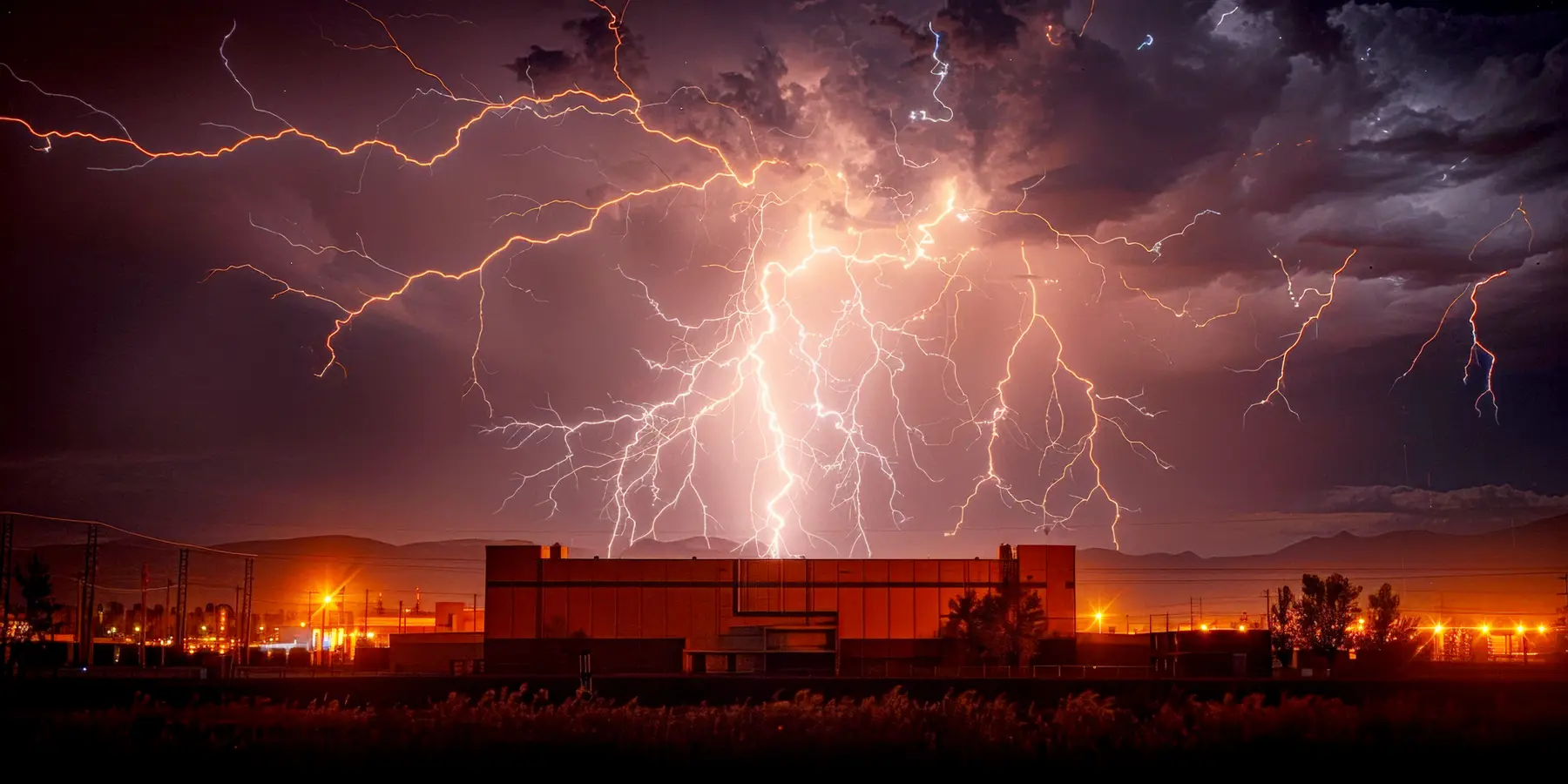
NFPA 780 solar rules sit in Chapter 12 of NFPA 780-2026. A rooftop or ground-mounted array exposed to direct strikes is protected to Chapter 4 plus Chapter 12: strike termination devices on the rack or beside the array, never on a panel frame, surge protective devices (SPDs) on the PV dc and inverter ac circuits, and a bonded, grounded array structure.
NFPA 780-2026, the Standard for the Installation of Lightning Protection Systems, gives solar arrays their own chapter, and it applies on top of Chapter 4. The sections below take each Chapter 12 rule in turn: device placement on an exposed array, a new array on a roof that already has protection, grounding a field array, PV surge protection, and whether a risk assessment comes first.
The standard is sold by the NFPA, and you need the official document to design, install or certify a system. Lumex is independent of the NFPA.
Does NFPA 780 cover solar panels?
Yes. Solar arrays are named in the scope of NFPA 780-2026 and have their own chapter, which applies alongside Chapter 4.
Arrays are in scope
Section 1.1.1 lists solar arrays among the installations the standard covers. Section 12.1 applies Chapter 12 to arrays on roofs and on the ground, both photovoltaic and solar thermal, together with their electrical and mechanical systems.
What counts as an array
A solar array is a group of PV modules or thermal collectors connected into a string or a larger system (3.3.39). A solar panel is the general word for one module or collector (3.3.40). Annex A notes that collectors make heat while modules make dc electricity.
The generation exception
NFPA 780 protects structures, not generation, transmission or distribution equipment. Section 1.1.2 makes Chapter 9 (wind) and Chapter 12 (solar) the stated exceptions, which is why a PV plant's arrays and inverters get specific rules here.
Chapter 12 does not stand alone. Section 12.2.1 says an array exposed to direct strikes is protected to Chapter 4, as supplemented by Chapter 12. Materials, conductor sizes, fasteners, connectors and grounding electrodes all still come from Chapter 4. Chapter 12 adds the array-specific rules on top.
How do you protect a solar array from direct strikes?
NFPA 780-2026 gives two routes, and protection uses one or the other (Section 12.2.2). The first is to fix strike termination devices to the array rack itself, shown in Figure 12.2.2(a). The second is to stand the protection beside the array, using air terminals, masts or overhead ground wires placed so the panels fall inside a zone of protection determined under Section 4.7, shown in Figure 12.2.2(b).
The standard leans towards the second route where you have the choice. Its explanatory note A.12.3.3 says it is better to keep lightning conductors as far as you can from the panels, controls and cabling, because a strike to devices mounted on the racking can go on to damage the array. If rack mounting cannot be avoided, the note points you to more shielding, more separation or more surge protection for the array's electrical and mechanical systems.
Whichever route you choose, devices may go on the rack but never directly on a panel frame (Section 12.3.3), and where practicable they are placed to limit shading of the panels (Section 12.3.4). An array already inside a zone of protection needs no devices of its own (Section 12.3.1); one outside it follows the placement rules below (Section 12.3.2). For how zones are drawn, see the NFPA 780 zone of protection and rolling sphere.
Where strike termination devices go on an exposed array
When an array is outside any zone of protection, its slope and size decide the placement rule. The values below are as printed in NFPA 780-2026, each cited to its section.
| Array shape | Placement rule, in our words | Section |
|---|---|---|
| Sloped array, height: a run up to 40 ft (12 m) sloped at 1/8 (7.5 degrees) or more, or a longer run at 1/4 (15 degrees) or more | Devices stand at least 10 in. (250 mm) above the top edge | 12.3.2.1 |
| Sloped array: devices at the apex ends | A device no farther than 24 in. (600 mm) from each end of the apex, and every device kept that close to the apex line | 12.3.2.1 |
| Sloped array: spacing | Spacing along the apex up to 20 ft (6 m); devices standing at least 24 in. (600 mm) higher than the apex may be up to 25 ft (7.6 m) apart along the top edge | 12.3.2.1 |
| Shallow array, corner devices: slope under 1/4 (15 degrees) and more than 20 ft (6 m) from top edge to bottom edge along its face | A device within 24 in. (600 mm) of each outer corner, unless that corner is already protected | 12.3.2.2 |
| Shallow array: edge spacing | Spacing along every edge up to 20 ft (6 m); devices at least 24 in. (600 mm) taller than the edge may be up to 25 ft (7.6 m) apart. Protected edges are exempt | 12.3.2.2 |
| Large shallow array: slope under 1/4, wider and longer than 50 ft (15 m) | Either devices across the array at spacings up to 50 ft (15 m), in the pattern of Figures 4.6.5.1(a) and (b), or taller devices placed so the rolling sphere never touches the array | 12.3.2.3 |
The 50 ft (15 m) field spacing mirrors the flat roof rule of Section 4.6.5.1, and the rolling sphere alternative mirrors Section 4.6.5.2. The rolling sphere's striking distance may not exceed 150 ft (45 m) (Section 4.7.3.1.4). For spacing and height rules on the building itself, see NFPA 780 air terminal spacing.
Rooftop solar on a building that already has lightning protection
NFPA 780-2026 answers this in three steps. First, check the zone. An array wholly inside the zone of protection of the existing air terminals needs no devices of its own (Section 12.3.1). Tilted rows can stand well above the roof, so redraw the zone with the array in place rather than reading it off the original drawings.
Second, deal with the metal. Section 12.5.2.1 asks for the array to be bonded under Section 4.14, and Section 12.5.2.2 asks for it to be made electrically continuous. The explanatory note A.12.5.2.2 suggests the grounding and bonding methods of Part V of NEC Article 690 as one way to get that continuity. Where the array's metal structure forms part of the lightning protection system, or sits within the required separation distance from it, that structure must be made continuous to Chapter 4 (Section 12.5.2.3). The separation distance comes from the bonding distance formulas of Section 4.15; see NFPA 780 grounding and bonding.
Third, connect the new protection properly. Any roof conductors that join the strike termination devices protecting the panels need their own down conductors and grounding electrodes under Chapter 4 (Section 12.5.2.4), and they must tie into the building's existing lightning protection system (Section 12.5.2.5). A separate island of air terminals over the array, left unconnected to the rest of the roof system, does not meet the chapter.
Grounding a ground-mounted solar array
A field array has no building to lean on, so NFPA 780-2026 gives it its own grounding rules, split by whether the racking carries lightning current.
A ring around every array
An array with a metallic structure is grounded with a ground ring electrode around its perimeter, built to Section 4.12.4, which puts the ring at least 18 in. (450 mm) deep in direct contact with earth or in a concrete footing (4.12.4.1). Other Section 4.12 electrodes may be added to the ring (12.5.1.1.1).
Neighbouring rings joined
Where two ground-mounted systems sit within 25 ft (7.6 m) of each other, their ground rings are interconnected, so adjacent arrays share one potential instead of two.
Racking used as the conductor
Where the racking itself serves as part of the protection system, make it electrically continuous using the Section 4.18.3 methods: bonding plates, welding, brazing, or drilling and tapping, on metal cleaned back to bare.
Racking not used as the conductor
Where the structure is not part of the system, each separate row or structure is bonded once directly to the ground ring, and the array is still made electrically continuous. Note A.12.5.1.4 points to Part V of NEC Article 690 as one way to do it.
A note printed with Figure 12.2.2(a) adds that NEC Article 690 separately requires the exposed metal parts of a solar panel to be grounded. NFPA 780 handles the lightning current, and the NEC handles the electrical safety grounding.
What surge protection does a PV system need under NFPA 780?
Section 12.4.2.1 makes surge protection of PV systems and their dc circuits a requirement, not an option. The table shows where each device goes and what it must meet.
| Location | What NFPA 780-2026 asks for | Section |
|---|---|---|
| PV dc circuits | Surge protection installed for the PV system and its dc circuits | 12.4.2.1 |
| Each PV SPD | A 20 kA 8/20 µs nominal discharge current (In) on each mode; listed for PV use and marked PV SPD, DC PV or DC | 12.4.2.1.1, 12.4.2.1.2 |
| PV SPD ratings | V_pvdc at least the maximum PV system voltage under NEC Article 690; short-circuit rating at least the prospective fault current; voltage protection rating per mode no more than three times the maximum PV system voltage | 12.4.2.1.4 to 12.4.2.1.6 |
| Two-port PV SPDs | Load current rating at least the current the system delivers to the inverter | 12.4.2.1.7 |
| Every PV SPD | Kept within its maximum rated ambient temperature | 12.4.2.1.8 |
| Inverter dc input, long runs | Additional PV SPDs on the PV output circuit next to the inverter when it sits over 100 ft (30 m) away from the nearest combiner or recombiner box | 12.4.2.1.3 |
| Ac module systems | Listed SPDs meeting Section 4.19 and Part II of NEC Article 242, located at the PV system disconnect | 12.4.2.2.1 to 12.4.2.2.3 |
| Inverter ac output | SPD to Section 4.19 with a 20 kA 8/20 µs In on each mode, short-circuit rating at least the inverter's prospective fault current, voltage protection rating within Table 4.19.2.7 (or three times the inverter's ac output voltage above that table's systems), maximum rated ambient temperature not exceeded | 12.4.3.1 to 12.4.3.6 |
| Building service | SPDs at every power service, integral to or right beside the service equipment, rated at least 20 kA 8/20 µs on each phase | 4.19.2.1, 4.19.2.1.1, 4.19.2.6 |
Section 12.4.1 frames the devices within a wider set of measures, applied where practicable: keep the separation distance and bonding of Sections 4.14 and 4.15, keep lightning conductors as far from the array and its cabling as you can, fit SPDs close to the array, the inverters and any tracker controls, shield the PV output cabling with braid, mesh or bonded metal conduit, trays or raceways, and route lightning conductors outside the PV cable path. For the general SPD rules, see NFPA 780 surge protection.
Separation also changes which SPD the PV circuit needs. Informative Annex K explains that when the separation distance to the modules cannot be kept, the air terminals must be bonded to the rack and the PV output circuit becomes one of the paths lightning current takes to ground (K.3). It maps that case to IEC test class I devices, and the separated case to class II (K.4). Because the IEC class I waveform is not referenced in NFPA 780, it suggests 8/20 µs devices with proportionately higher In ratings where the two systems are bonded. For the IEC classes, see SPD types under IEC 62305.
The 2026 edition changed these rules. Against the 2020 edition, the 2026 text states the dc surge requirement more generally, adds the DC PV marking, changes the short-circuit rating from coordinated with the fault current to not less than it, and adds Section 12.4.2.2 for ac module systems. Chapter 4 cross-references were renumbered too, for example the zone of protection moved from Section 4.8 to 4.7 and surge protection from 4.20 to 4.19. This compares the 2020 and 2026 editions. The 2023 edition was not compared. See NFPA 780-2026 changes.
What about wind turbines on a solar site?
Wind turbines have their own chapter, Chapter 9 of NFPA 780-2026, which protects the tower, nacelle and hub but not the blades or the generating equipment (Sections 9.1 and 9.1.2); note A.9.1.2 leaves those to manufacturer product approval standards. Nacelle air terminations are placed under Section 4.7 with the blades turned to give the smallest zone of protection (9.2.1), structural parts serve as air terminals and conductors where possible (9.2.2), and the hub cover gets a strike termination device (9.2.5). Designers are asked to consider bonding, shielding and separation for the control systems (9.3.1), and each turbine's common grounding system ties into the site grounding system where one exists (9.4).
Annex A adds background: A.9.1 describes tip receptors and says the blade maker normally builds blade protection into the blade, and A.9.2.6 notes that a tubular metal tower usually meets the down conductor dimensions and can be treated as an effective electromagnetic shield. IEC 61400-24 appears only among the informational references of Annex O (O.2.1), not in Chapter 9's requirements. For how wind and solar sites are assessed as a whole, see lightning risk assessment for renewable energy.
Common mistakes an inspector will find
Most mistakes start when an array is added to a roof whose zone of protection was drawn without it.
Assuming the old zone still covers the array
Tilted rows can stand taller than the air terminals that protected the bare roof. Section 12.3.1 relieves only panels that are actually inside a zone, so redraw it with the array in place.
Air terminals clamped to panel frames
Section 12.3.3 allows devices on the rack but not fixed directly to the frame of a panel, and A.12.3.3 prefers keeping the devices off the racking altogether.
An island of air terminals
Roof conductors protecting the panels need down conductors and grounding, and must connect to the building's system (Sections 12.5.2.4 and 12.5.2.5). An unconnected set over the array is a gap, not protection.
Ac-rated SPDs on dc circuits
PV SPDs must be listed for PV use and carry the DC, DC PV or PV SPD marking, with a V_pvdc rating at or above the maximum PV system voltage (Sections 12.4.2.1.2 and 12.4.2.1.4).
One ring for a whole field
Section 12.5.1.1 asks for a ground ring around each array's perimeter, and rings within 25 ft (7.6 m) are interconnected. A single loop around the site boundary does not meet it.
No record for the next inspection
Informative Annex D recommends a visual inspection at least once a year and a complete inspection every 3 to 5 years (D.1.1.2). As good practice, not a Chapter 12 requirement, keep a drawing of the zone of protection with the array in place and a record of the bonding and continuity checks. See the NFPA 780 inspection checklist.
Does a solar site need a risk assessment first?
Chapter 12 tells you how to protect an array. It does not tell you whether the site needs protection. That question belongs to Annex L, the NFPA 780-2026 lightning risk assessment, which is informative and has no solar-specific inputs. You assess the structure the array sits on, or the site's buildings, with the same quick screen (L.5) and detailed assessment (L.6) used for any structure.
Three clauses frame the answer for solar owners. L.1.1.1 puts statutory, regulatory and insurance requirements ahead of the risk result, so a contract or insurer can decide the question outright. L.5.3.1 lists energy facilities, power plants among them, as critical facilities, and L.5.3.2 says a critical facility should either be protected to the standard or taken through the detailed assessment. Whether a given PV plant counts as a power plant for that list is a judgment for the owner and the authority having jurisdiction. For the method in full, read NFPA 780 Annex L, section by section.
Where Lumex fits on a solar project
On an NFPA 780 solar project, Lumex runs the NFPA 780-2026 Annex L risk assessment, the quick screen and the detailed R1 to R4 assessment, for the building under a rooftop array or the structures on a solar site. It shows the working behind every figure and produces a signed-off report. When you first generate the report, it sets a review-due date 12 months later for NFPA 780, unless you have already set one, and sends a reminder as it comes up.
Lumex does not design the Chapter 12 installation: it does not place air terminals, size conductors, lay out ground rings or select SPDs, and it does not certify an installation. Periodic inspection reports are coming soon. The design stays with your lightning protection designer. Start with the Annex L screen for the building under the array, then give the result to your designer.
Related reading: how Lumex runs the NFPA 780 risk assessment, which lightning standard applies to your project, NFPA 780 explained chapter by chapter, and, for an Australian site, lightning protection for solar PV in Australia.
NFPA 780 solar questions answered
Does NFPA 780 cover solar panels?
How do you protect a rooftop solar array from lightning under NFPA 780?
Does a solar array on a roof that already has lightning protection need its own air terminals?
What surge protection does NFPA 780 require for a PV system?
How do I protect a solar inverter from lightning under NFPA 780?
How is a ground-mounted solar array grounded under NFPA 780?
What does NFPA 780 say about wind turbines?
Does NFPA 780 require a risk assessment before protecting a solar array?
Lumex computes the method of the standard you choose, IEC 62305-2:2024, AS 1768:2021 or NFPA 780-2026, and shows the working. It does not certify a structure. You may not issue or submit a Lumex output until a competent person, qualified where the structure is located, has reviewed the inputs and the result and signed it.
NFPA 780-2026 Annex L gives default tolerable values of 1E-5 per year for loss of life or injury and 1E-3 for loss of service and of historical significance, and the owner or the authority having jurisdiction may set others. Every NFPA 780 assessment in Lumex states the values that applied.
Get started today