NFPA 780 tanks: protecting flammable liquid and vapor storage
NFPA 780 tanks fall under Chapter 7 of NFPA 780-2026. A sealed, electrically continuous metal tank protects itself when its walls are no thinner than 3/16 in. (4.8 mm), per 7.2.2. An external floating roof tank needs sliding contacts, bypass conductors and bonded or insulated seal parts (7.6.2).
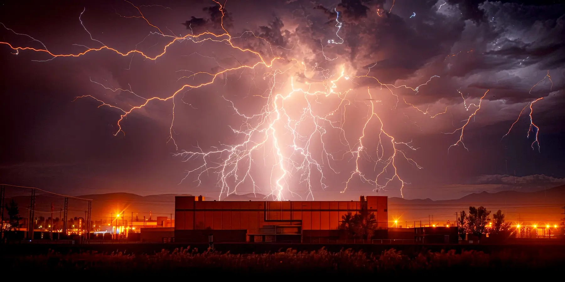
NFPA 780 tanks rules live in Chapter 7 of NFPA 780-2026, which covers any structure that holds flammable vapors or gases, or liquids that release them, and adds tank-specific detail to the general requirements of Chapter 4.
The chapter puts vapor control first (7.2.1.1), accepts that a thick, sealed metal tank protects itself (7.2.2), and spends most of its length on the weak points: floating roof seals, vents, gauge poles and the joint between roof and shell.
Every value below is read from NFPA 780-2026 and was checked against it on 30 September 2026. Lumex is independent of NFPA, and you need the standard itself, bought from NFPA, to design or certify a system.
Which NFPA 780 tanks and structures does Chapter 7 cover?
Chapter 7 applies wherever flammable vapor or gas is present or can form, not only to storage tanks.
In scope
Storage tanks, pressure vessels, process structures, tank batteries and earthen containers that hold flammable vapors or gases, or liquids that give them off. Annex note A.7.1.1 ties this to Class I hazardous (classified) locations as NFPA 70 Article 500 defines them, in all or part of a structure.
Out of scope
Nonmetallic tanks. NFPA 780-2026 sends them to Annex N, which is informative guidance rather than a requirement. Annex note A.7.8 repeats the point for tank batteries built from nonmetallic tanks.
Existing tanks (retroactivity)
Section 1.4.1 applies the standard to new work unless a clause says otherwise. Section 7.1.3 brings the Section 1.4 retroactivity rules into Chapter 7, and annex note A.7.1 leaves the timing of upgrades to the authority having jurisdiction (AHJ). A.7.1.3 recommends upgrading at a rebuild, a major floating roof repair or a full seal replacement.
The first line of defense is not a conductor. Section 7.2.1.1 makes vapor control the primary measure. It names four ignition routes: a direct strike, an upward streamer, the electromagnetic pulse of a nearby flash (LEMP) and secondary arcing. Keep flammable mixtures away from likely ignition points, close or flame-protect openings that release them, and keep hatches, vent valves and roof seals in working order (7.2.1.2 to 7.2.1.4).
When is a metal tank self-protecting?
Under NFPA 780-2026 Section 7.2.2, a metal structure is inherently self-protected when three things are all true. It is electrically continuous. It is sealed tight enough that liquid, vapor and gas cannot escape. Its metal is no thinner than 3/16 in. (4.8 mm), enough to take a direct strike without being burned through. Section 7.5.1 applies the same idea to sealed tanks and vessels under pressure, as long as the vessel is grounded, and words the thickness as more than 3/16 in.
Wall thickness is the easy part. Annex note A.7.2.2 lists the everyday features that defeat self-protection: vents that break the seal, valves and fittings where secondary arcing can occur, a floating roof poorly bonded to the shell, primary and secondary seals that let vapor out, electronics that need surge protective devices, and any shape that lets vapor pool. The note says truly self-protected structures are uncommon for exactly these reasons.
Two more limits apply. Exposed valves on a pressure vessel still count in the decision (7.5.2). A steel tank with a wooden or other nonmetallic roof is never self-protecting, however well sealed or sheathed the roof is (7.6.3).
What does each tank type need under NFPA 780-2026?
For NFPA 780 tanks and related structures, find the row that matches, then read the clause. The table summarises; it does not replace the text.
| Tank or structure | What NFPA 780-2026 asks for | Clause |
|---|---|---|
| Sealed metal tank or vessel under pressure, grounded, walls over 3/16 in. (4.8 mm) | Treated as self-protecting. Exposed valves and fittings still weigh in the decision. | 7.5.1, 7.5.2 |
| Fixed roof metal tank (cone or dome) | No sliding or fixed contact conductors required. Vapor at the vents is the concern. | 7.6.1, A.7.6.1 |
| Tank with an internal floating roof | No sliding or fixed contact conductors required. | 7.6.1 |
| External floating roof tank | Sliding contacts (metallic shoe seals or shunts), bypass conductors, and bonding or 1 kV insulation of seal parts and gauge poles. | 7.6.2 |
| Metal tank with a wooden or nonmetallic roof | Not self-protecting. Strike termination devices bonded to each other, to any sheathing and to the shell. | 7.6.3 |
| Earthen container with a combustible roof | Protection by air terminals, masts, overhead ground wires or any mix of them. | 7.7.1 |
| Tank battery | Protection covers the associated equipment, site appurtenances outside the zone of protection, and ground-level equalization. | 7.8 |
| Process structure, not storage | Section 7.3 in full, unless a lightning risk assessment justifies otherwise. | 7.4.1 |
| Nonmetallic tank | Outside Chapter 7. Informative guidance only. | 7.1.2, Annex N |
What does a protection system for a flammable vapor structure include?
Section 7.3 is the baseline for any structure that is not self-protecting. It keeps the Chapter 4 materials and methods (7.3.1) and tightens them in six places.
A smaller striking distance. The zone of protection uses a striking distance no greater than 100 ft (30 m) (7.3.2), tighter than the general 150 ft (45 m) ceiling of Section 4.7.3.1.4. How that changes the geometry is covered in the guide to the NFPA 780 zone of protection.
Where the strike lands. Strike termination devices follow Section 4.5 (7.3.3.1), placed with sparks and impact at the attachment point in mind (7.3.3.2).
Down conductors outside the hazard. Run them outside the hazardous (classified) location where you practicably can (7.3.4.2). Where you cannot, the conductor must not heat the vapor past its autoignition temperature (7.3.4.3). Annex note A.7.3.4.3 suggests an unspliced run, and a nonmetallic enclosure rated for the area where that temperature is 160 °F (70 °C) or lower.
Bonding beyond the minimum. Section 7.3.5 asks you to go past the bonding rules of Sections 4.13 to 4.15 as far as needed so that no melting or spraying of metal happens anywhere except the point where the strike attaches.
Surge protection, placed with care. Surge protection for equipment and services follows NFPA 70 and Section 4.19 (7.3.6.1). Put it outside hazardous locations where practicable (7.3.6.2); inside one, it goes in an enclosure identified for that Class and Division (7.3.6.3). The detail is in the guide to surge protection under NFPA 780.
Grounding. The default is a ground loop conductor or ground ring electrode, plus electrodes from Sections 4.12.2 to 4.12.7 (7.3.7.1). It is not required for a structure whose perimeter is 200 ft (60 m) or less (7.3.7.2). Metal tanks have their own options, set out next.
Grounding NFPA 780 tanks: how is a metal tank grounded?
Section 7.3.7.3 accepts four routes. Any one of them satisfies the clause.
Through grounded piping
Bond the tank to a grounded metal piping system at two points or more, with no insulated joints in between. Annex note A.7.3.7.3(1) says buried pipe counts as an electrode only when it is continuous and in contact with earth for 10 ft (3 m) or more.
By its own footing
A vertical, flat-bottom tank that sits on earth, bitumen or concrete is grounded by that contact. Annex note A.7.3.7 lets a large tank stand in for the ground ring: 20 ft (6 m) diameter or more on earth or concrete, 50 ft (15 m) or more on bituminous pavement.
With dedicated electrodes
At least two grounding electrodes of the Section 4.12 types, as far apart as practicable and spaced 100 ft (30 m) or less around the perimeter.
To the site grounding system
At least two connections to a site grounding system, spread as widely around the perimeter as practicable.
Two rules catch designers out. First, A.7.3.7.1 exempts tanks, and structures for petroleum production, processing and storage, from the general ground ring rule of 7.3.7.1, so tanks rely on the 7.3.7.3 routes. Second, A.7.3.7.3 says an insulating containment membrane under a tank does not change the choice of method, although supplemental grounding helps protect the membrane itself. Section 7.3.7.4 says these grounding rules apply only to the lightning protection system. For electrode types in general, see NFPA 780 grounding and bonding.
Floating roof tanks: shunts, bypass conductors and seals
An external floating roof moves up and down with the product, so the path from roof to shell has to survive that movement and still carry lightning current.
NFPA 780-2026 splits the job between two kinds of connection. Sliding contacts, meaning metallic primary shoe seals or shunts, carry the short and intermediate parts of the stroke current (A.7.6.2.1). Fixed contacts, the bypass conductors, carry the intermediate and long-duration parts (A.7.6.2.2). A tank needs both, and the values below are the ones the 2026 edition prints.
| Item | NFPA 780-2026 value or rule | Clause |
|---|---|---|
| Metallic primary shoe seal | Bonded to the roof by its construction, or by at least one Class I conductor or equivalent | 7.6.2.1.1 |
| Shunt material (nonconductive primary seal) | Flexible stainless steel, 0.031 in.2 (20 mm2) or larger in cross section, or another material with equal current capacity and corrosion resistance | 7.6.2.1.2(1) |
| Shunt width | At least 2 in. (50 mm) | 7.6.2.1.2(2) |
| Shunt spacing | No more than 10 ft (3 m) apart around the roof perimeter | 7.6.2.1.2(3) |
| Shunt contact, ordinary service | Touches the shell 12 in. (300 mm) or more below the liquid surface | 7.6.2.1.2(8) |
| Shunt contact, tanks run drain-dry | Shunts sit above the roof deck | 7.6.2.1.2(8) |
| Retrofit to submerged shunts | Remove the old above-deck shunts | 7.6.2.1.2(8) |
| Bypass conductor size | The cross section of a main-size conductor, or larger | 7.6.2.2.1 |
| Bypass conductor resistance | No more than 0.03 ohm end to end, connectors included | 7.6.2.2.2 |
| Number of bypass conductors | At least two, and one for each 100 ft (30 m) of perimeter or part of it, evenly spaced | 7.6.2.2.4 |
| Rolling ladder | One bypass runs along the ladder, bonded to it, as a single continuous length from roof to shell | 7.6.2.2.5, 7.6.2.2.6 |
| Seal parts above the liquid (springs, scissors, membranes) | Bonded to the roof, or insulated from it at 1 kV or more | 7.6.2.3 |
| Gauge poles, guide poles and telescoping legs through the roof | Bonded to the roof, or insulated from it at 1 kV or more | 7.6.2.4 |
Shunts take the shortest, most direct path from roof to shell (7.6.2.1.2), and both shunts and bypass conductors are only as long as the roof's full travel needs (7.6.2.1.2, 7.6.2.2.3). For service life, the annex notes (A.7.6.2.1.2(7), A.7.6.2.2.7) point to API RP 545, which they say recommends at least 30 years. Main-size conductor dimensions come from Chapter 4.
How does NFPA 780 treat nonmetallic tanks?
Fiberglass and plastic tanks sit outside Chapter 7 (7.1.2). Annex N of NFPA 780-2026 covers them instead, and it is informative: guidance, not requirements. Its opening advice is blunt. Where flammable vapor may be present, the annex recommends not using a nonmetallic tank at all, and it presents its measures as ways to reduce lightning damage rather than prevent it (N.1).
The shell insulates, holds static charge and lets electromagnetic fields through, so even a sound Chapter 4 system leaves very high voltages on the metal fittings, and an unbonded fitting can sideflash (N.1). Annex N suggests five measures:
- A rolling sphere radius of 100 ft (30 m) or less for direct strike protection (N.2).
- A flexible bond across every insulating gasket at hatches, joints, flanges and valves (N.3.1).
- Every metal fitting bonded to the others with at least a minimum-size main conductor, and the group connected to ground or a grounded structure (N.3.2, N.3.3).
- Charge neutralization for tanks that receive produced water and gas, using the API and NFPA 77 documents the annex lists (N.4).
- The grounding of each tank in a multi-tank battery bonded to the others, directly or through continuous metal walkways (N.5).
Where engineering analysis supports it, N.6 adds a Faraday-like enclosure working together with the bonding, grounding and surge suppression to limit field effects on the tank.
What does NFPA 780 Chapter 8 require for explosives?
Chapter 8 of NFPA 780-2026 sets the minimum protection for structures housing explosive materials. It does not apply to Hazard Division 1.4 materials, to quantities of 25 lb (11.3 kg) net explosives weight or less, or where a risk assessment justifies leaving it out (8.1.1). It also steps aside where protection would conflict with airfield or flightline operations, as the AHJ decides (8.1.2).
The design striking distance is again 100 ft (30 m) (8.2.1). Protection takes one or more of four forms: a grounded metallic, Faraday-like cage where the AHJ wants protection from LEMP (8.3.2), masts (8.3.3), overhead wire or catenary systems (8.3.4), or strike termination devices on the structure itself (8.3.5). A ground ring electrode is required (8.4.1) unless the structure covers 500 ft2 (46.5 m2) or less or a single mast or air terminal protects it (8.4.1.1). The ring sits at least 3 ft (1 m) from the foundation and carries at least two ground rods (8.4.2.2, 8.4.2.3).
Every power, signal, data and communications line entering or leaving the building needs surge protection (8.6), and power and metallic communications lines arrive in shielded cable or metal conduit buried for at least 50 ft (15 m) (8.6.1). Chapter 8 also sets its own fixed maintenance intervals: a visual inspection at least once every 7 months (8.9.6), an electrical test no less often than every 14 months (8.9.7), and no more than 200 milliohms dc resistance for any single bonded object (8.9.7.1). The NFPA 780 inspection checklist covers the general regime these tighten.
Common mistakes with NFPA 780 tanks
The weak points the 2026 edition itself names (A.7.2.2) are small gaps in sealing, bonding and upkeep, not missing air terminals.
Calling a tank self-protected on thickness alone
Section 7.2.2 has three conditions, not one. An open vent, a worn seal or an unbonded floating roof fails the test however thick the shell is (A.7.2.2).
Shunts without bypass conductors
Shunts and bypass conductors do different jobs (A.7.6.2.1, A.7.6.2.2). An external floating roof needs both, and the bypass count grows with the perimeter (7.6.2.2.4).
Gauge poles and seal parts forgotten
Anything conductive that passes through or rides on the roof is bonded to it or insulated at 1 kV or more (7.6.2.3, 7.6.2.4). A pole left neither bonded nor insulated is the kind of fitting A.7.2.2 names as a place for secondary arcing.
A 150 ft sphere on a vapor structure
Chapter 7 caps the striking distance at 100 ft (30 m) (7.3.2), and Chapter 8 designs to 100 ft (30 m) (8.2.1). A layout checked with the general 150 ft (45 m) sphere leaves gaps.
Maintenance treated as optional
Section 7.2.1.4 makes keeping hatches, vent valves and roof seals in working order part of the protection, so maintenance records belong in the file next to the drawings.
How flammable contents change the NFPA 780 risk assessment
Section 7.4.1 requires the full Section 7.3 measures for operating facilities that are not storage, unless a lightning risk assessment justifies otherwise. Annex L of NFPA 780-2026, which is informative, sets out one method for that assessment, and flammable contents move its inputs sharply.
In the quick screen, the contents coefficient C3 is 3.0 for exceptional value contents such as flammable liquids (Table L.5.1.2(b)). Section L.5.3.1 lists hazardous material storage, operating and processing facilities, and energy facilities such as fuel refineries, as critical facilities, and L.5.3.2 says those should either be protected to the standard or carried through the detailed assessment of Section L.6.
In the detailed assessment, a risk of explosion changes four things at once. It brings the components R_Z, R_W, R_M and R_C into R1, loss of life (the note to L.6.5). It sets the fire reduction factor r_f to 1 (Table L.6.7.12), the provisions factor r_p to 1 (Table L.6.7.11), and the typical loss L_O to 0.1 (Table L.6.7.9). A special hazard factor h_Z of 7 applies to explosives storage in approved magazines and to production of flammable or combustible materials (Table L.6.7.13). One more point from annex note A.7.4.1: Annex L does not model several lightning protection zones in one structure, and the note recommends IEC 62305-2 where only part of a structure is hazardous.
The risk decision, not the tank hardware
Lumex runs the Annex L assessment of NFPA 780-2026 on its Voltrace engine: the quick screen and the detailed assessment of R1 to R4, each judged against its own tolerable value. When you record that a structure carries a risk of explosion, Voltrace applies every factor that answer controls, and the report names the table behind each one. That record is one way to show the lightning risk assessment Section 7.4.1 refers to when an operating facility departs from Section 7.3.
Lumex does not design the system. It does not size shunts, count bypass conductors, lay out grounding or certify a tank. Those stay with the engineer and the standard. Lumex sets a review-due date and reminder 12 months out for every NFPA 780 assessment. An explosives facility under Chapter 8 also needs a visual inspection at least every 7 months (8.9.6), which you schedule outside Lumex.
To start, open an NFPA 780 assessment for the tank farm and record whether each structure carries a risk of explosion.
For how the whole assessment runs, see NFPA 780 risk assessment in Lumex, or which standard applies to your site. Related reading: the Annex L risk assessment, section by section, NFPA 780-2026 chapter by chapter, air terminal spacing and Class I and Class II materials, what changed in the 2026 edition, and the IEC 62305 view of oil, gas and hazardous sites.
Questions answered
Do metal tanks need lightning protection under NFPA 780?
What are shunts on floating roof tanks?
What is a bypass conductor on a floating roof tank?
How does NFPA 780 treat nonmetallic tanks?
How is a metal fuel tank grounded under NFPA 780?
Does a fixed roof tank need shunts?
What does Chapter 8 of NFPA 780 cover?
Does an existing tank have to be upgraded to the 2026 edition?
Lumex computes the method of the standard you choose, IEC 62305-2:2024, AS 1768:2021 or NFPA 780-2026, and shows the working. It does not certify a structure. You may not issue or submit a Lumex output until a competent person, qualified where the structure is located, has reviewed the inputs and the result and signed it.
NFPA 780-2026 Annex L gives default tolerable values of 1E-5 per year for loss of life or injury and 1E-3 for loss of service and of historical significance, and the owner or the authority having jurisdiction may set others. Every NFPA 780 assessment in Lumex states the values that applied.
Get started today